Magnetic Particle Inspection Machine for Crankshafts: Equipment Selection and Customization Guide
Crankshafts are critical components in automotive engines, heavy-duty machinery and other industrial equipment. During forging, machining, heat treatment and service, cracks and other discontinuities may develop on or near the surface. Reliable inspection is therefore important before components proceed to the next manufacturing stage or enter service.
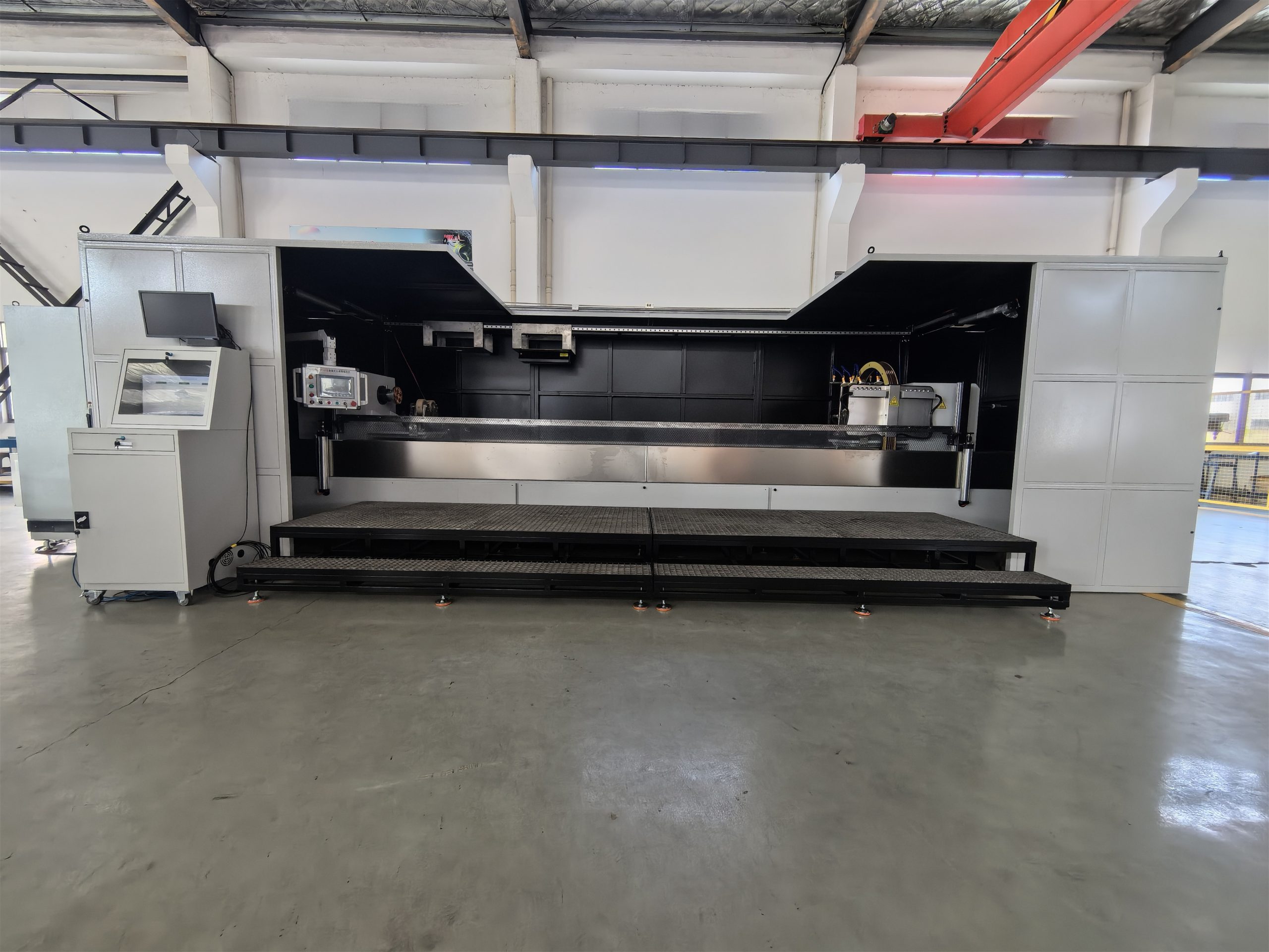
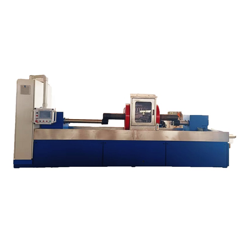
A magnetic particle inspection machine for crankshafts must be designed with more than the overall workpiece length and diameter in mind. Other considerations include the geometry of the crankpins and main journals, fillet areas, workpiece rotation, magnetization directions, fluorescent magnetic particle application and demagnetization requirements.
NEWK NDT specializes in manufacturing magnetic particle inspection equipment and customized non-destructive testing (NDT) systems. For crankshaft inspection applications, the equipment configuration should be determined according to the actual workpiece drawings, inspection procedure, applicable acceptance criteria and production requirements.
1. Why Do Crankshafts Require Specialized Magnetic Particle Inspection Equipment?
Unlike conventional cylindrical shafts, crankshafts have an offset structure consisting of main journals, crankpins, crank webs and fillet transitions. These features make workpiece positioning, magnetic field application and visual examination more challenging than inspection of standard shaft-shaped components.
A properly configured crankshaft magnetic particle inspection machine should address the following requirements.
Inspection of Different Crankshaft Areas
The inspection procedure may cover main journals, crankpins, fillet radii and other specified surfaces. The fixture and workpiece support system should allow operators to access and examine the required inspection areas.
Depending on the crankshaft design, the equipment may require adjustable supports, suitable clamping arrangements or controlled workpiece rotation.
Detection of Cracks in Different Orientations
Magnetic particle inspection is suitable for detecting surface and near-surface discontinuities in ferromagnetic materials. Detection effectiveness depends on the orientation of a discontinuity relative to the applied magnetic field.
Since cracks in crankshafts may occur in different orientations, the inspection procedure must establish appropriate magnetization directions and sufficient magnetic field strength for the areas being examined.
Consistent Inspection for Production Applications
For batch production, inspection repeatability is important. Magnetization parameters, magnetic particle application, inspection timing and demagnetization should be controlled according to the approved inspection procedure.
For higher-volume applications, programmed operating sequences and automated workpiece handling can help reduce repetitive manual operations.
2. Magnetization Methods for Crankshaft Magnetic Particle Inspection
Magnetization is one of the most important considerations when selecting a crankshaft magnetic particle inspection machine. The equipment must generate a suitable magnetic field in the areas requiring inspection.
Circular Magnetization
Circular magnetization produces a magnetic field around the workpiece. In a typical bench-type arrangement, current passes through the component between two electrical contact points.
This method can reveal discontinuities oriented approximately perpendicular to the resulting magnetic field. Contact locations, current parameters and crankshaft geometry must all be considered during equipment design.
For crankshaft inspection, the clamping arrangement should provide reliable electrical contact while minimizing the risk of contact marks or localized overheating.
Longitudinal Magnetization
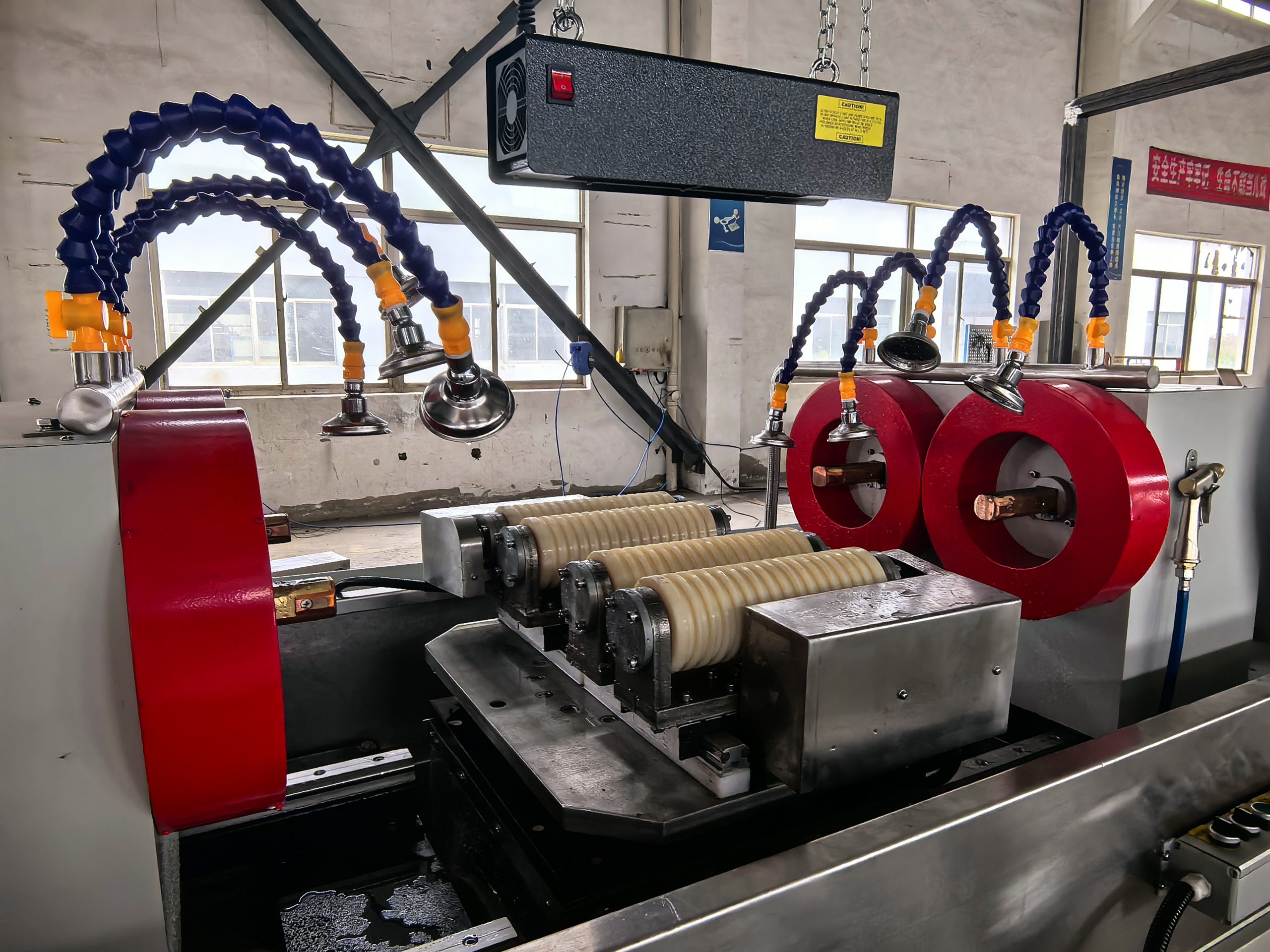
Longitudinal magnetization produces a magnetic field along the length of the workpiece, commonly using an encircling coil.
This field direction helps reveal discontinuities with orientations different from those targeted by circular magnetization. Coil diameter, coil position and the placement of the crankshaft within the coil all influence the inspection setup.
Combined or Multidirectional Magnetization
Some crankshaft applications require more than one magnetization direction to achieve the specified inspection coverage.
Depending on the inspection procedure, the equipment may use separate magnetization shots or a combined or multidirectional magnetization arrangement. These methods are not interchangeable in every application. The required field directions, magnetization sequence, timing and verification method must be established for the actual workpiece.
When selecting a custom magnetic particle inspection machine for crankshafts, specify the required magnetization method rather than choosing equipment based solely on its maximum current rating.
3. Key Features to Consider in a Crankshaft Magnetic Particle Inspection Machine
The appropriate equipment configuration depends on crankshaft dimensions, weight, geometry, required inspection coverage and production cycle time. The following features should be evaluated during the technical selection process.
Workpiece Clamping and Positioning
The headstock, tailstock or other fixture arrangement must securely accommodate the crankshaft. The design should consider the distance between contact points, workpiece length, rotational envelope and accessibility of the inspection surfaces.
For large or heavy crankshafts, loading and unloading may require a crane or other material-handling equipment. Smaller workpieces may be suitable for manual loading, depending on their weight and handling requirements.
Adjustable Coil Positioning
If longitudinal magnetization is required, the coil position and diameter should match the workpiece envelope and inspection procedure.
For crankshafts with different lengths or geometries, adjustable coil positioning can help reduce changeover time. The adjustment range and operating method should be defined during the equipment specification stage.
Magnetic Particle Application System
Wet magnetic particle inspection requires an appropriate system for preparing and applying the magnetic particle suspension. The equipment may include a suspension tank, circulation pump, spray nozzles and a recovery system.
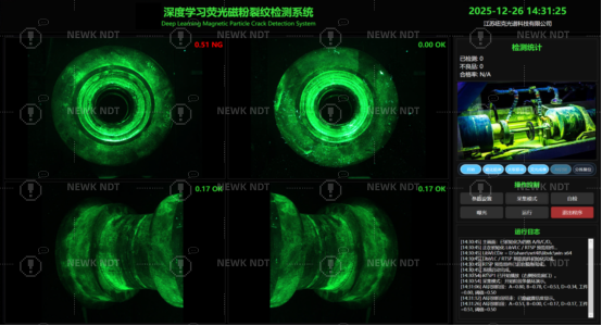
For fluorescent magnetic particle inspection, the inspection area must also provide suitable UV-A irradiance and ambient lighting conditions in accordance with the applicable inspection procedure.
The particle application and observation arrangements should allow operators to access the required inspection surfaces without obstructing their view.
Controlled Inspection Sequence
Depending on the level of automation, the machine may control workpiece clamping, rotation, particle application, magnetization timing and demagnetization.
A semi-automatic system may retain manual loading and visual evaluation while automating selected operations. A more highly automated system may integrate additional workpiece handling and process-control functions.
The level of automation should be determined by actual production requirements rather than by the number of automated functions available.
Demagnetization Function
Residual magnetism may affect subsequent machining or assembly operations. Where required by the inspection procedure, the machine should incorporate a suitable demagnetization method.
The customer should specify the required residual magnetism limit and verification method. Demagnetization performance must be evaluated against the applicable technical requirements rather than assumed from the presence of a demagnetization function alone.
4. How to Specify the Right Magnetic Particle Inspection Machine for Crankshafts
Providing detailed application information helps the equipment manufacturer evaluate a suitable configuration and avoid unnecessary equipment costs.
| Specification | Information Required |
|---|---|
| Workpiece type | Engine crankshaft, industrial crankshaft or other component |
| Material | Steel grade or other ferromagnetic material specification |
| Workpiece dimensions | Overall length, maximum diameter and rotational envelope |
| Workpiece weight | Minimum, maximum and typical workpiece weight |
| Inspection areas | Main journals, crankpins, fillets and other specified surfaces |
| Defect requirements | Expected discontinuity types and orientations |
| Magnetization method | Circular, longitudinal, combined or other specified arrangement |
| Inspection method | Fluorescent wet magnetic particle inspection or visible magnetic particle inspection |
| Production volume | Required number of components per shift or per day |
| Cycle time | Required inspection time per component |
| Demagnetization requirements | Residual magnetism limit and verification method |
| Automation level | Manual, semi-automatic or automatic |
| Applicable standards | Customer specifications and relevant inspection standards |
Providing drawings or clear photographs of the actual crankshaft is particularly helpful. These materials allow the equipment manufacturer to evaluate fixture design, electrical contact locations, coil dimensions, workpiece rotation and accessibility of the inspection areas.
5. What Determines the Price of a Crankshaft Magnetic Particle Inspection Machine?
The price of a magnetic particle inspection machine for crankshafts depends on the complete equipment configuration rather than a single electrical rating.
Key cost factors include:
- Magnetization capacity: Required current, ampere-turns, current type and duty cycle.
- Workpiece dimensions: Maximum length, diameter, weight and fixture requirements.
- Magnetization arrangement: Contact-based circular magnetization, coil-based longitudinal magnetization or a specified combined system.
- Magnetic particle application system: Tank capacity, circulation, spraying and recovery arrangements.
- Demagnetization system: Required method and performance.
- Inspection environment: UV-A lamps, a darkroom enclosure and lighting measurement equipment, where applicable.
- Automation level: Positioning mechanisms, PLC control, touchscreen operation and material-handling systems.
- Additional requirements: Data recording, integration with an existing production line, installation and commissioning.
To obtain a meaningful quotation, provide the workpiece details, inspection requirements and required scope of supply. Comparing machines solely by maximum current may overlook important differences in inspection capability and included functions.
6. Customized Magnetic Particle Inspection Equipment from NEWK NDT
NEWK NDT specializes in manufacturing magnetic particle inspection equipment and customized NDT systems. Equipment configurations can be evaluated according to the customer’s workpiece dimensions, inspection procedure, production targets and automation requirements.
For crankshaft inspection projects, the first step is a technical review of the workpiece and the required inspection process. Before issuing a final technical proposal, the feasibility of the proposed configuration, magnetization arrangement, fixture design and inspection sequence should be confirmed.
To help us evaluate your project, please provide the following information:
- Crankshaft drawings or clear photographs
- Material, dimensions and weight
- Required inspection areas and acceptance criteria
- Applicable inspection standards or customer procedures
- Expected production volume and cycle time
- Required magnetization and demagnetization methods
- Preferred automation level
- Electrical supply and installation conditions
Based on this information, we can discuss the proposed equipment configuration and determine the next steps for a technical quotation.
Contact NEWK NDT to discuss your crankshaft magnetic particle inspection equipment requirements.
Email: irene@nksmartmeter.com