In industries such as manufacturing, aerospace, and energy, non-destructive testing (NDT) is a crucial tool for ensuring material and structural integrity. Fluorescent penetrant testing (PT), a classic surface defect inspection method, is widely favored for its high sensitivity and cost-effectiveness. The term “fluorescent penetrant” refers to the liquid used during testing, which seeps into surface-breaking defects via capillary action and emits a fluorescent signal under ultraviolet (UV) light, enabling the identification of cracks, porosity, and other micro-defects.
This guide explores the principles, operational procedures, applications, and 2025 technology trends of fluorescent penetrant testing, offering practical insights to improve inspection efficiency and accuracy. Whether you are an NDT practitioner or an engineering manager, this guide will help enhance your inspection processes.
Keywords: Fluorescent penetrant testing, penetrant, non-destructive testing, PT method, surface defect detection
1. What is Fluorescent Penetrant Testing? Its Unique Role in NDT
Non-destructive testing (NDT) evaluates material integrity and detects internal or surface defects without compromising functionality. Fluorescent penetrant testing, a branch of penetrant inspection, is specifically designed to detect surface-breaking defects in non-porous materials such as metals, plastics, and ceramics. It uses fluorescent penetrants that seep into defects and fluoresce under UV light, allowing observation even in dark environments.
Compared with other NDT methods, fluorescent PT focuses on qualitative and quantitative analysis of surface micro-defects, making it ideal for thin-walled or complex-shaped components. Its key advantage is high sensitivity, capable of detecting cracks as shallow as 0.1 mm. According to GB/T 18851 series standards (e.g., GB/T 18851.2-2008 for penetrant testing materials), this method is standardized in aerospace, pressure vessels, and other critical applications.
Comparison: Fluorescent vs. Visible Penetrant Testing
| Aspect | Fluorescent Penetrant Testing (PT-F) | Visible Dye Penetrant Testing (PT-V) |
|---|---|---|
| Indication Medium | Fluorescent penetrant (UV-activated) | Visible dye (natural light) |
| Sensitivity | High (detects micro-defects) | Medium (suitable for rough surfaces) |
| Observation Environment | Darkroom + UV lamp (365 nm) | Natural light |
| Typical Applications | Precision parts, aerospace components | Castings, weld inspections |
| Cost | Higher (requires specialized equipment) | Lower (simpler operation) |
Fluorescent penetrants enable precise defect localization, significantly improving quality control efficiency.
2. Five Core Steps of Fluorescent Penetrant Testing: Detailed Procedure
Fluorescent PT follows the PTES (Penetrant Testing Execution Standard) framework and typically involves five stages. Each step emphasizes surface cleanliness and environmental control to ensure effective penetrant infiltration.
Step 1: Surface Preparation – Remove Contaminants
Thoroughly clean the workpiece to remove oil, rust, or coatings to ensure the penetrant can enter defects.
- Techniques: Use alkaline degreasers or ultrasonic cleaning, maintaining temperatures between 10–50°C (per GB/T 18851.5-2014).
- Tips: In low-temperature environments (<10°C), preheat the workpiece above 15°C to prevent penetrant solidification (GB/T 18851.6-2014).
Step 2: Penetrant Application – Infiltrate Defects
Apply fluorescent penetrant evenly via spraying or immersion, allowing 10–30 minutes for capillary action to draw the liquid into cracks.
- Recommended Materials: Water-washable or solvent-removable fluorescent penetrants (e.g., Magnaflux Spotcheck series) with low viscosity and high fluorescence.
- Tips: Adjust dwell time according to defect size; for complex geometries, brush application ensures complete coverage.
Step 3: Excess Penetrant Removal – Prepare for Development
Gently rinse or wipe off surplus penetrant while leaving defect-filled penetrant intact.
- Techniques: Use flowing water for water-washable penetrants; avoid high-pressure washing that could flush out penetrant from defects. For solvent-removable types, wipe with lint-free cloth.
- Common Mistake: Over-cleaning may result in false negatives.
Step 4: Developer Application – Visualize Defects
Apply dry or wet developer to form a thin white layer that draws penetrant from defects, producing fluorescent indications.
- Developer Choice: Non-aqueous wet developers for high-precision inspections; drying time 5–10 minutes.
- Observation: Use UV lamps (blacklight) in a darkroom; defects appear as yellow or green fluorescence.
Step 5: Inspection and Reporting – Evaluate Results
Observe fluorescent indications under UV light, document defect location, size, and type, clean the part, and generate an inspection report.
- Standards: Defect evaluation follows ASTM E1417 or GB/T 18851.1.
- Digital Enhancement: Use UV cameras for automated documentation, improving report efficiency.
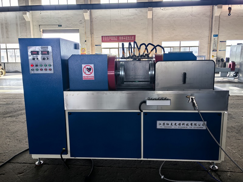
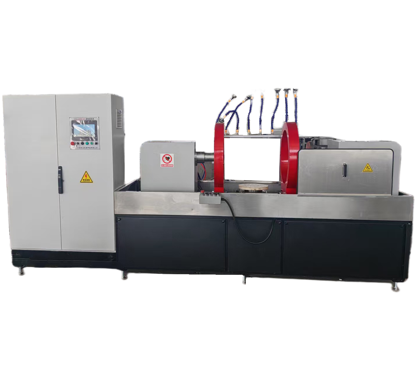
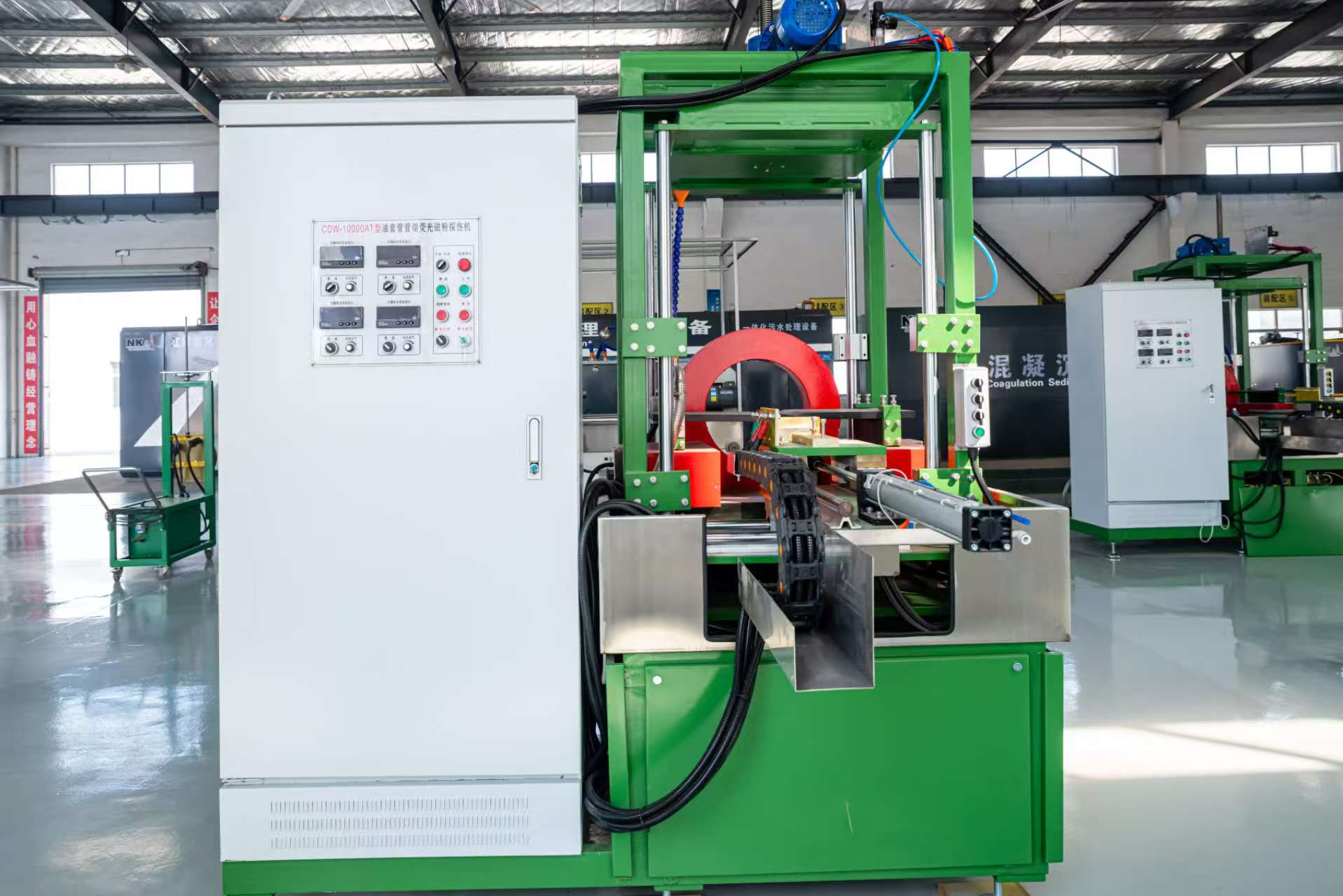
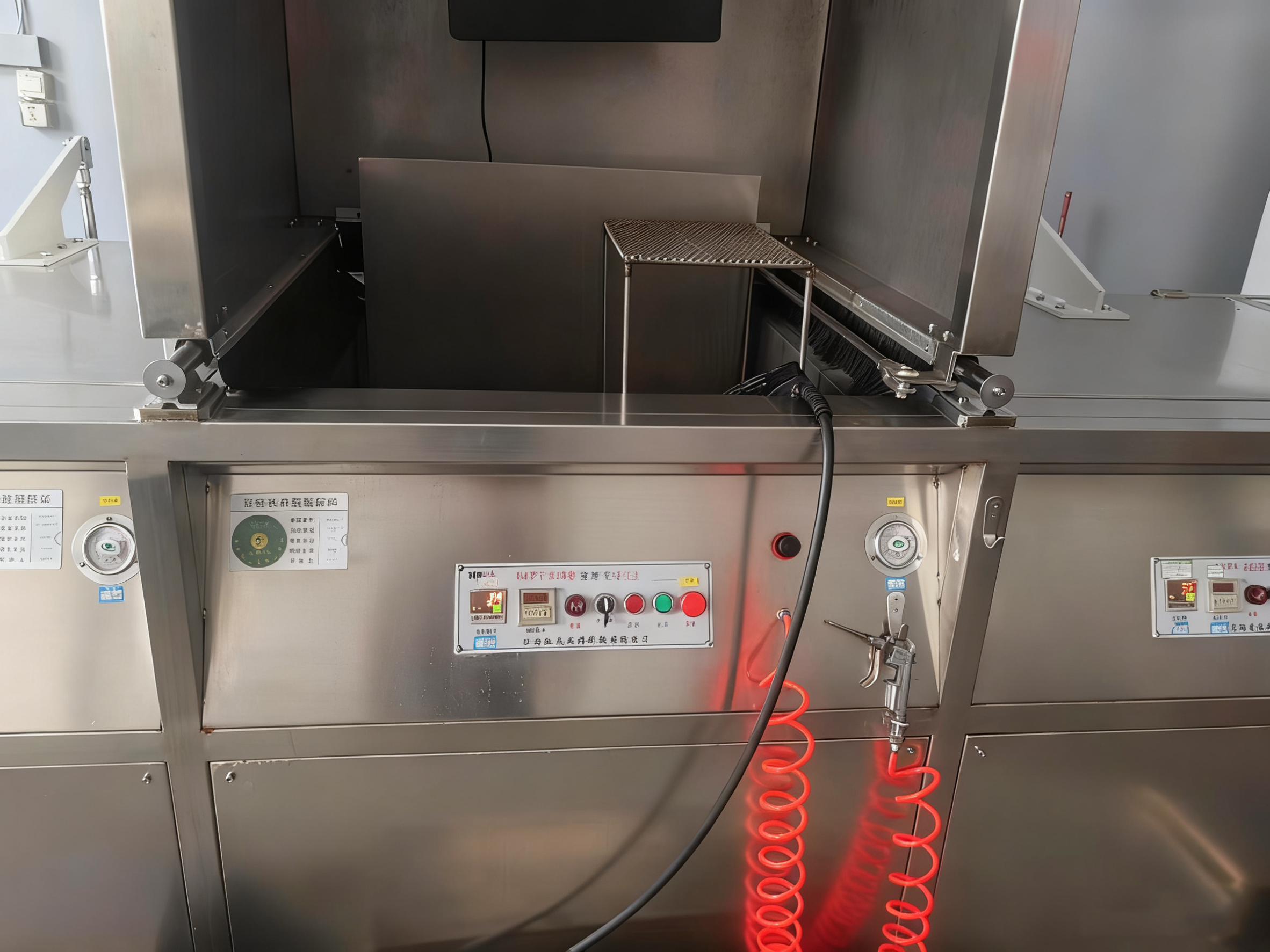
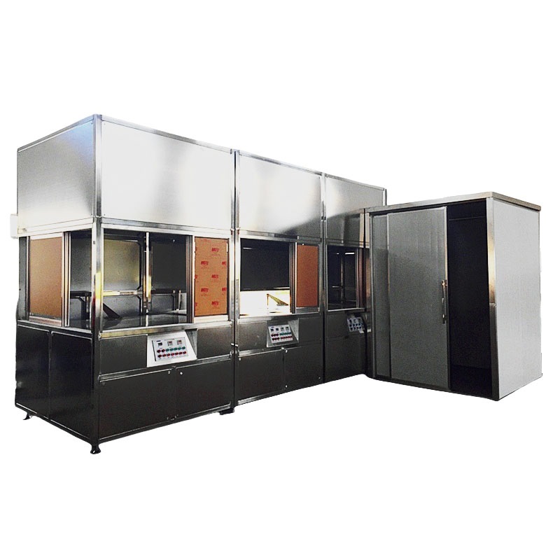
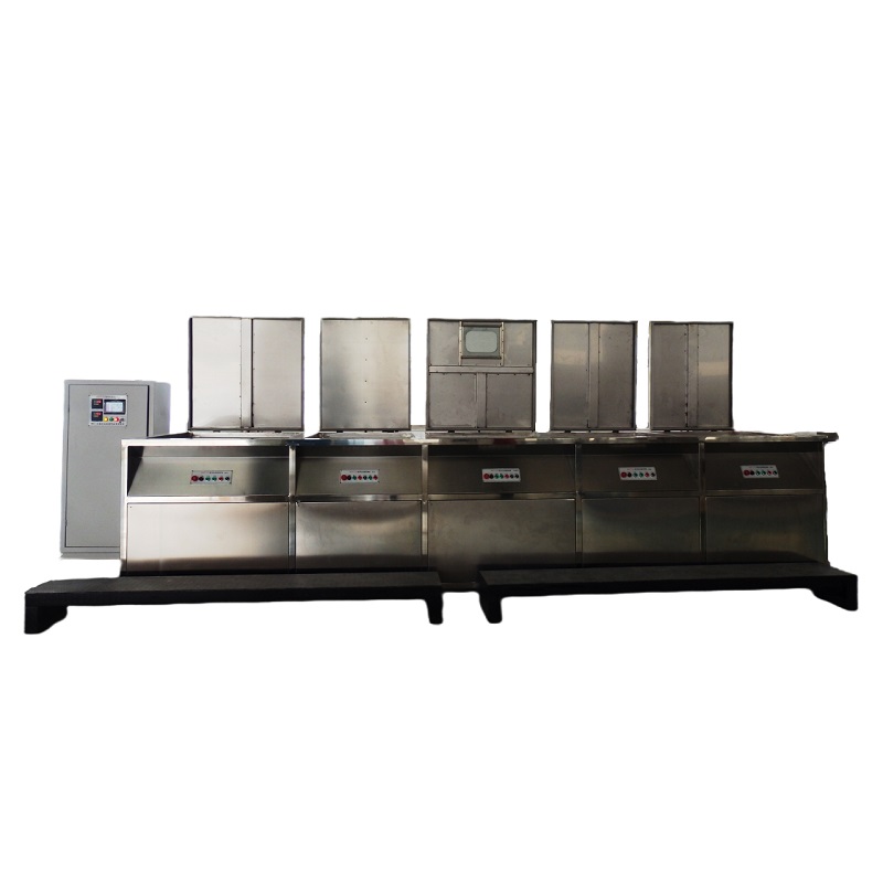
3. Fluorescent PT Tools in 2025: Automation and AI Integration
With AI and automation, fluorescent PT is becoming smarter and more efficient. Key 2025 tools include:
- Magnaflux QPL Series: Integrated solution with UV lamps, ideal for aerospace inspections.
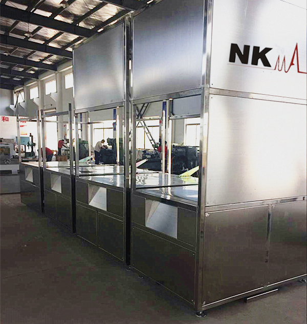
- China NK NDT: original manufacture; excellent cost-performance; customized solution
- AI-enhanced PT Scanners (e.g., Aramis PT-AI): Automated defect recognition for mass production.
These systems can integrate with Python-based image analysis scripts (e.g., OpenCV for fluorescent image processing) to further improve detection accuracy.
4. Applications and Limitations of Fluorescent PT
Core Applications
- Aerospace: Detect cracks in turbine blades, ensuring flight safety.
- Pressure Vessels: Inspect welds and castings in compliance with ASME standards.
- Automotive Manufacturing: Surface inspection of engine components to enhance reliability.
- Emerging Fields: Surface damage detection on composites (e.g., wind turbine blades) with infrared assistance.
Limitations
Fluorescent PT is limited to surface-breaking defects and cannot detect volumetric defects like inclusions. Complementary NDT methods (e.g., ultrasonic testing) may be required. In-service inspections can effectively monitor fatigue cracks, but high humidity (>95%) conditions necessitate specially formulated penetrants.
Case Study: A leading aerospace company increased defect detection by 25% using fluorescent PT, saving over $1 million annually in maintenance costs.
5. 2025 Trends: Smart, Green, and Digital PT
By 2025, fluorescent PT is trending toward eco-friendly and digital solutions:
- Low-VOC Penetrants will reduce environmental impact.
- AI-driven real-time fluorescent image analysis will minimize human error.
- Cloud-based platforms (e.g., SGS PT Cloud Services) enable remote reporting, improving global supply chain efficiency.
- China’s NDT market is projected to grow 15%, with domestic equipment accounting for over 60% market share.
6. Conclusion: Master Fluorescent Penetrants, Safeguard Industry
Fluorescent PT is the “surface guardian” of NDT, providing efficient and precise visualization of defects. Combining standardized procedures with advanced tools significantly reduces risk and prolongs product life. Beginners should start with GB/T 18851 series standards, while experienced practitioners may pursue certifications such as CEH. Integrating fluorescent PT with other NDT methods builds a comprehensive inspection system.
References: Based on 2024–2025 NDT standards and market reports.